


Synchronization
Synchronization Behavior with Distributed Clocks (DC) Enabled
With DC enabled by the EtherCAT master, the drive synchronizes to the master’s Sync0 signal.
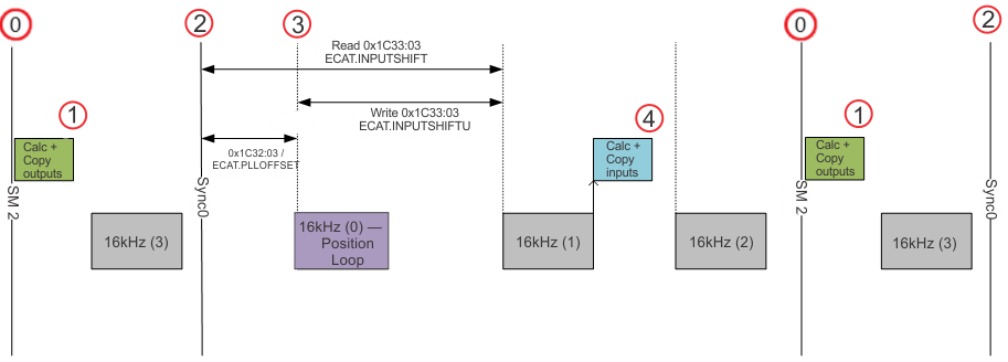
Below is an example of a synchronized fieldbus cycle with 4kHz cycle time:
|
|
These two keywords/EtherCAT objects can be used to influence the synchronization behavior of the drive.
- ECAT.PLLOFFSET (Index 1C32h Sub-Index 3): Configures a delay between the Sync0 signal (2) and the 16kHz interrupt that runs the position loop (3) up to 250 uS. If the SM2 event has too much jitter or occurs too close the Sync0, the position loop may run before processing updated data. This offset can be adjusted to shift the position loop to allow more time to process the data.
- After modifying this value, the EtherCAT state machine must be reset back to PREOP to resynchronize the Phase-Locked Loop (PLL).
- ECAT.INPUTSHIFTU (Index 1C33h Sub-Index 3): Configures the offset between the first 16kHz after the Sync0 signal and the 16kHz interrupt that triggers the TxPDO. A value of -1 means the drive calculates the offset automatically once the drive synchronizes in OP to be 125 to 187 uS before the drive expects the SM2 event. If the packet jitter is low and consistent, the default timing should be sufficient to provide the latest feedback data in the input packet. If packet jitter is too large, the input time may need to be shifted to account for the jitter.
- The diagram above shows timing with ECAT.INPUTSHIFTU set to 62,500 ns. If ECAT.INPUTSHIFTU was the default -1, the input packet is triggered in 16kHz tick 0 because it calculates two 16kHz samples from when the SM2 event occurs at (1).
- The value, while in ns, is required to be written by a factor of 62,500 ns (16kHz intervals)
- When writing ECAT.INPUTSHIFTU, the value does not account for the PLL offset, while reading ECAT.INPUTSHIFT includes the PLL offset in the time.
- The EtherCAT object, when written, writes the user offset time (ECAT.INPUTSHIFTU). When read, it reads the actual offset time (ECAT.INPUTSHIFT) and may not match the written value exactly.
Diagnostic keywords can be used to read DC system timestamps of certain events that help determine the correct synchronization settings:
- ECAT.RXIRQTIME: The time the Rx PDO data was received from the master.
- ECAT.RXDONETIME: The time the drive finished copying Rx PDO data from the master.
- ECAT.SYNC0TIME: The time of the Sync0 signal.
- ECAT.POSLOOPTIME: Start time of the 16kHz interrupt that runs the position loop.
- ECAT.TXDONETIME: The time the drive finished calculating and copying TxPDO data to be sent in the next cyclic frame.
- ECAT.INPUTSHIFT: Shows the current input offset in ns after sync0 is used for sending PLC inputs. This value is only valid once in OP after the drive has synchronized to the master.
- CANOPEN.LOOPBACK: There are PDO mappable objects ‘Rx Loopback’ (300Bh sub-index 4) and ‘Tx Loopback’ (300Bh sub-index 3) that can be monitored from the Programmable Logic Controller (PLC) to verify synchronization. When the Rx Loopback is updated from the PLC, the drive should mirror the value in the Tx Loopback back to the PLC on the next fieldbus cycle. If the value does not match the Rx Loopback then synchronization should be investigated as it means the drive is not transmitting updated data correctly in relation to the received data.
Synchronization Behavior with DC Disabled
- When DC is disabled, the synchronization behavior is configured with the keyword ECAT.USEPLL.
-
With ECAT.USEPLL set to the default value of 1, the drive will synchronize the position loop to the SyncManager2 event. The SyncManager2 event is created when the EtherCAT Master sends a new packet of command values to the drive while the network is in the Operational state, which occurs once per fieldbus cycle.
- With ECAT.USEPLL set to 0, the drive is not synchronized to the master and uses a local timer.
- ECAT.PLLMODE is read to determine the synchronization method currently used by the drive.
-
ECAT.PLLOFFSETNODC can be used to adjust where the drive latches the output values with respect to the SM2 event. By default, the offset is set to 125uS to allow for some packet jitter.
Example WorkBench Synchronization Measurements and Adjustments
Default
Using a default project in TwinCAT running at 2 ms, it configures an SM2 offset of ~600uS prior to sync0. The drive aligns the position loop with sync0 and configures the input offset to be ~125 uS prior to the SM2 event. A recording can be setup in WorkBench using the system time keywords mentioned above to view how the drive responds and verifies the events line up correctly as shown below.
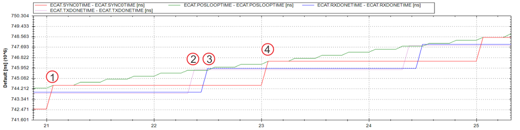
- At time (1) Sync0 is 744,503,524 ns, the position loop runs at 744,505,084 ns: 1.56 uS after sync0.
- At time (2) TXDONETIME (PLC inputs) is prepared at 745,806,603 ns: 1.303 ms after sync0 and ~125uS prior to the SM2/RXDONETIME event as configured by default in the drive.
- At time (3) RXDONETIME (PLC outputs) is processed at 745,918,323 ns: 1.414 ms after sync0, ~600uS prior to the next sync0, as configured in TwinCAT.
- At time (4) the next Sync0 cycle starts at 746,503,524 ns: exactly 2 ms after the previous cycle.
PLL Offset
If RXDONETIME is inconsistent, indicating SM2 jitter, and overruns Sync0/POSLOOP times, an offset can be applied to the drive PLL to shift where the position loop occurs with respect to Sycn0.
The recording below shows the RXDONETIME (blue) completing after the POSLOOPTIME (green), indicating the SM2 event was received too late to apply outputs in the position loop associated with Sync0.
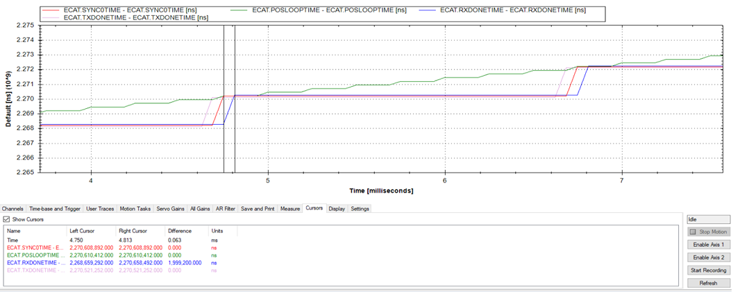
Set ECAT.PLLOFFSET = 125000 ns to shift the position loop to occur after Sync0 by 125 uS which causes it to occur after the RXDONETIME.
In the recording below, now RXDONETIME (blue) occurrs before the POSLOOPTIME (green) indicates the position loop is running with the latest data.
Input Shift
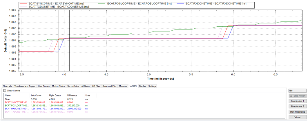
If TXDONETIME occurs after the SM2 time due to SM2 jitter, it can be shifted to occur prior to the SM2 event for better synchronization.
In the recording below, the TXDONETIME (purple) occurs after RXDONETIME (blue). The PLC receives the previous cycle’s feedback data because the input packet is filled out at the SM2 event time, which is only a few microseconds before RXDONETIME.

The TXDONETIME should be well before RXDONETIME. If there is jitter in RXDONETIME, make sure to shift TXDONETIME by enough to account for it. For this example, TXDONETIME is 125 uS before RXDONETIME. Determine what value to set ECAT.INPUTSHIFTU to be a time from Sync0 prior to RXDONETIME time by 125 uS.
Use the recording to determine the value:
Rx sync0 offset – 125,000 ns > (RXDONETIME – SYNC0TIME) – 125,000 ns > (2,446,177 ns – 1,027,556 ns) – 125,000 ns > 1,418,621 ns – 125,000 ns = 1,293,621 ns.
Because the drive can only transmit on a 16kHz tick, adjust this time to a factor of 62,500 ns. In this case, round down and set ECAT.INPUTSHIFTU = 1,250,000 ns.
In the recording below, the TXDONETIME (purple) now indicates it has completed 1.313 ms after Sync0 (red) and 125 uS before RXDONETIME (blue). The Tx was triggered at 1.250ms as configured and completed by the next 16kHz recording tick.


